Vermont Energy Control Systems

Practical monitoring and control for the real world

Sequence Manager

Sequence Manager

Vermont Energy Control Systems

Practical monitoring and control for the real world

Sequence Manager

Introduction

Important: This software is in beta test!

This capability is in the development and test phase. It will only be available if manually instaled by Vermont Energy Control Systems. As beta software, it should be carefully monitored at all times, and any unexpected behavior or problems should be reported immediately. Do not trust this capability to run critical systems without supervision.

This document covers the Vesta Sequence Manager, also known as the Recipe Engine. The Sequence Manager allows the specification of a sequence of steps, with specific actions to be taken at each step and criteria for moving from step to step.

The Sequence Manager typically works in conjunction with the Rule Engine, and interacts with data elements. This document assumes familiarity with Rule Programming and Terminology.

For your convenience, there is a table of contents at the top of each page in this manual as well as the option to view the entire manual as a single page (the 'All Pages' link at the end of the table of contents). The topics covered are as follows:

  • Concepts Basic concepts and terminology for the Sequence Manager.
  • Editing Modifying, adding, and deleting recipe segments.

Disclaimer: This documentation is under construction. Every effort is being made to ensure that it is accurate and complete. However, it is entirely possible that it may contain errors and omissions. If you see a problem, please contact Vermont Energy Control Systems.

Sequence Manager Concepts

Vermont Energy Control Systems

Practical monitoring and control for the real world

Sequence Manager

Concepts And Terminology

Actions

'Actions' are the things that the Sequence Manager actually does. They have the form 'Set x to y'. An action always sets a Vesta data element to a specified numeric value. If you're setting a discrete output or state variable, use 0 for false and 1 for true. Actions can set any variable or Vesta output. Inputs cannot be set as their values come from the physical hardware.

Recipe Phases

Recipes are made up of multiple steps, called phases. Each phase has the same basic structure: "Start doing something. Keep doing it until you're done. Then, move on to the next phase". Consider cooking rice. One phase might be 'Heating the water', and the structure looks like this: "Turn on the stove to start heating. Keep heating until it boils, Then, add rice and move on to the cooking phase".

In the Sequence Manger, phases consist of two parts:

Phase example
  • Initial actions. These are the things that will happen when the phase first starts. Typically this will consist of turning outputs on or off, or setting values - 'Turn on the stove to start heating' in the example above, or the actions in the section titled 'When this phase starts' in the example at right. Initial actions are optional, but most phases include several.
  • Exit paths. These define how to move to another phase. Exit paths have criteria - 'How do I know this phase is done?' and one or more actions to be taken. The example at right has two exit paths: 'Normal Exit' and 'Operator Abort'.

Exit Paths

Each phase must have at least one exit path. Exit paths have two components:

  • Criteria - the condition under which this exit path will be used.
  • Actions - one or more actions to be taken when the exit criteria are met.
Every exit path must have at least one action: it must set a new value for the 'Current Phase' variable. In most cases that will simple be the next phase in sequence, but it's possible to skip phases or jump to any specific phase. The example at right has a 'Normal Exit' that goes to the next phase, but it also has an 'Operator' Abort' that takes it back to the initial 'Inactive' phase.

When an exit path is taken, that event is written to the Vesta log file.

Recipe Variables

Every phase has a unique 'index number' that the Sequence Manger uses to refer to and identify phases. The phase number is stored in a Vesta data element so that it can be monitored and logged.

Every recipe has a designated first phase. This is the recipe starting point, and it's usually a 'safe' state with everything turned off, closed, or otherwise stable.

Vesta recipe elements

Each recipe must be linked to three Vesta data elements that provide top level control of recipe execution. These elements can have any desired name. In the example at rights they're named 'Recipe Enable', 'Recipe Start', and 'Current Phase'.

  • Recipe Enable. This element must evaluate to 'true' before the Sequence Manager will perform any actions. If it becomes false during recipe execution, the Sequence Manager will effectively pause, taking no further actions until it's enabled again. This will most often be a state variable that's controlled by the user, but it could be a discrete input, a timer variable, or other data element that can reliably evaluate to 'true' or 'false'.
  • Recipe Start. When this element becomes true, the Sequence Manager will start the designated first phase. The element used for this function has the same criteria as 'Recipe Enable'.
  • Current Phase. This contains the index number of the phase that's currently active. This must be a normal variable (not a state variable).

Editing Recipes

Vermont Energy Control Systems

Practical monitoring and control for the real world

Sequence Manager

Editing Recipes

Recipe Files

Recipes are stored in text files - specifically, JSON formatted text files in the Vesta data directory. These can be hand-edited, but there's a web-based recipe editor that's available from the Vesta 'Elements & Rules' tab. This editor allows you to perform all of the basic editing functions:

Vesta recipe editing
  • Editing actions (affected data elements and values).
  • Editing exit criteria.
  • Changing the names or phases and exit paths.
  • Adding and deleting exit paths.
  • Adding and deleting phases.

There are some limitations. The editor cannot change the sequence of phases or exit paths, and it can't currently create new recipes or save under a different name.

Editing Names

Path names and phase names can be edited directly. Simply tab out of the field or hit 'enter' to submit your edit. Actions and exit criteria have multiple fields. Make your changes and click the 'Submit' button.

Deleting

The red X icon will delete the corresponding phase, action, or exit path. Note that the first phase in the recipe and the first exit for each phase cannot be deleted.

Inserting

The green arrow/+ icon inserts a new item of the corresponding type after the line with the icon. Inserted items will have placeholder names and values that will need to be edited.

Insert icons insert another item of the same type as the line they're on: an insert icon next to a phase name will insert a new phase. An insert icon next to an exit path will insert a new exit path, and icons next to actions will insert a new action.

Sequence Manager Concepts

Vermont Energy Control Systems

Practical monitoring and control for the real world

Sequence Manager

Recipe Example

This page describes an application example using the Sequence Manager to provide control of a variable speed pump.

Sample Recipe

Situation

A customer wanted a pump to be managed in a specific way to optimize system performance. He wanted a sequence as follows:

  1. When demand occurs, start at a user-defined low speed and ramp slowly to full speed.
  2. Stay at full speed for five minutes.
  3. Ramp down to a different user-defined speed.
  4. Stay at that speed until demand is satisfied.

The Vesta rule engine is not well suited to managing this kind of sequence. It’s possible, but the resulting variables and rules would be complicated and hard to understand.

The Vesta Sequence Manager is designed for exactly this situation: a sequence of steps with different operating conditions for each, and defined criteria for transitioning between steps. This application example describes the process of meeting the customer’s requirements using the Sequence Manager.

Approach

There is an analog output named ‘Pump Speed’ that drives the pump. It’s value is in percent. We need to provide values for this output, ramping it up and down and holding it at different fixed values.

Ramping Output

The easiest way to ramp an output with the Vesta is to have a math rule that adds an increment (or decrement) to the output every rule engine cycle. We’ll use a variable named ‘Ramp Increment’ to hold the increment value, which can be positive, negative, or zero. In this case the Sequence Manager will set the increment value depending on the phase.

Phases

There are five phases including the default phase 0. Each phase has defined criteria for transitioning to the next phase.

  1. Pump off, no demand
    • Transition to phase 1 when there’s a demand for the pump
  2. Ramp up to full speed
    • Transition to phase 2 when full speed is reached
  3. Hold at full speed
    • Transition to phase 3 after five minutes
  4. Ramp down to low speed
    • Transition to phase 4 when chosen low speed is reached
  5. Hold at low speed
    • Transition to phase 0 when there is no longer demand for the pump

It’s also possible that pump demand could go away during any phase. In that case, we want to ramp down, then stop. We’ll add transitions from phases 1 and 2 that go directly to phase 3 if the pump is no longer needed.

Variables

In addition to the ramp increment variable mentioned above, the Sequence Manager requires two variables: an ‘enable’ variable that allows it to be active, and a ‘phase’ variable to hold the current phase. In this case pump control should always be enabled, so we can choose the system 'TRUE' data element as our 'enable' element.

We’ll also need a state variable to tell the Sequence Manger when the pump is needed.

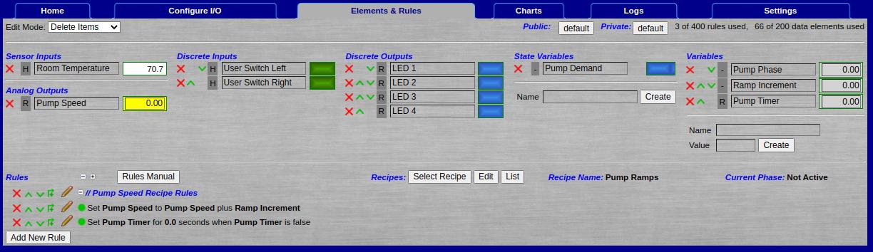
Finally, we’ll need a timer variable for the full speed phase. Here’s the complete list of Vesta data elements required for this application:

NameTypePurpose
Pump SpeedAnalog OutputVesta output that controls pump speed
TRUESystem ConstantKeeps the Sequence Manager always enabled
Pump DemandState VariableTells the Sequence Manager that the pump is needed
Pump PhaseVariableCurrent phase in the sequence
Ramp IncrementVariableAmount to change the speed each rule cycle
Pump TimerVariableTimer for the five minutes at full speed

Vesta Rules

We need two Vesta rules: One to increment the output, and one for the timer variable. Here they are:

Set Pump Speed to Pump Speed plus Ramp Increment
Set Pump Timer for 0.0 seconds when Pump Timer is false

The timer rule doesn’t do anything, but it is required to tell the rule engine that ‘Pump Timer’ is a timer variable that should count down.

Recipe

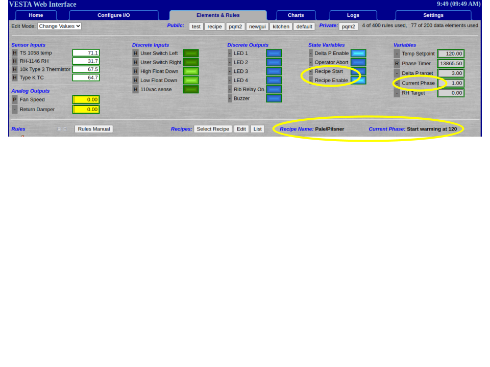
The recipe for this application has a data header and five phases. This is the actual recipe as displayed by the 'List' button, with explanations for each section.

Recipe Data Header

    Recipe Data:
        Name: Pump Ramps
        File Name: pumpramp.json
        Enable Variable: TRUE
        Phase Variable: Pump Demand
        First Phase: Not Active
    

This is all standard Sequence Manager data. Note the use of the 'TRUE' systrem constant as the enable variable.


Phase 0

    Phase 0: 'Not Active'
        When this phase starts:
            Set Pump Speed to 0
            Set Ramp Increment to 0

        Exit Path: 'Ramp Up'
            If Pump Demand EQ 1
              Set Pump Phase to 'Ramp Up'
    

This is the default inactive phase. This is the starting point and ending point. In this phase, the pump is off and the increment is zero. The only transition from this phase is to ‘Ramp Up’ when there’s demand for the pump.


Phase 1

    Phase 1: 'Ramp Up'
        When this phase starts:
            Set Pump Speed to 20
            Set Ramp Increment to 0.5

        Exit Path: 'Full Speed'
            If Pump Speed GT 98
                Set Pump Phase to 'Full Speed'
                Set Ramp Increment to 0

        Exit Path: 'No Demand'
            If Pump Demand EQ 0
                Set Pump Phase to 'Ramp Down'
    

Here we set the pump speed to 20% at first, and set the ramp increment to a positive value. This will result in the pump speed incrementing due to the rule that we created earlier. When we’re very close to full speed, we set the ramp increment to zero and go to the ‘Full Speed’ phase. If there’s no demand, we jump to the ‘Ramp Down’ phase.


Phase 2

    Phase 2: 'Full Speed'
        When this phase starts:
            Set Pump Speed to 100
            Set Pump Timer to 300

        Exit Path: 'Ramp Down'
            If Pump Timer EQ 0
                Set Pump Phase to 'Ramp Down'

        Exit Path: 'No Demand'
            If Pump Demand EQ 0
                Set Pump Phase to 'Ramp Down'
    

When this phase starts we set the speed to 100% and set the timer for 300 seconds (five minutes). The normal exit happens when the timer counts down to zero and we go to the ‘Ramp Down’ phase. If pump demand goes away, we jump immediately to ‘Ramp Down’ regardless of the timer.


Phase 3

    Phase 3: 'Ramp Down'
        When this phase starts:
            Set Ramp Increment to -0.5

        Exit Path: 'Low Speed'
            If Pump Speed LT 50
                Set Pump Phase to 'Low Speed'
    

Here we set the ramp increment to a negative value so that the output will decrement. Our target low speed in this case is 50%, and we’ll exit when the output reaches this value. We use ‘Less Than’ in case the value is never exactly equal to 50%. We’ll exit with a value slightly less than 50%.


Phase 4

    Phase 4: 'Low Speed'
        When this phase starts:
            Set Ramp Increment to 0
            Set Pump Speed to 50

        Exit Path: 'Normal Exit'
            If Pump Demand EQ 0
                Set Pump Phase to 'Not Active'
    

In this phase we set the speed to the desired value (it was a bit less on entry). This phase continues until there’s no demand for the pump, at which time it transitions to Phase 0. Note that if there’s no demand when this phase begins, it will transition immediately.


Discussion

In this example the 'low' speed (50%) is embedded into the recipe, so that changing it's value would require editing the recipe. It would also be possible to use a variable to hold this value. However, the Sequence Manager does not support variables as the second argument to actions or exit criteria. For instance, even if you have a variable named 'Slow' with a value of 50, you can't have an action like this:

Set Pump Speed to Slow

It's possible to have a state variable that's set by the Sequence Manager, and then use a standard rule to actually set the value. For instance, create a state variable called 'Force Slow Speed'. You can then create a Sequence Manager action and standard rule like these:

Sequence Manager action: Set Set Slow Speed to 1

Standard Rule: Set Pump Speed to Slow when Force Slow Speed is true

Of course, the Sequence Manager would need to set 'Force Slow Speed' back to false at some point.