
In many Vesta installations, thermostats are part of the picture. There are a great many varieties, but most follow a basic design that's documented here. As is the case for all material on this site, this is a general reference. Look at the manufacturer's documentation for details on your specific device.
Thermostats and heating system controls usually work on a 24VAC signal. There is a transformer (or perhaps more than one) either inside a piece or equipment or mounted on an electrical junction box, usually near the equipment being controlled. Thermostats usually draw their power from this 24VAC supply, and they provide a 24VAC signal to activate one or more relays in the equipment being controlled. This diagram shows a simplified schematic with the common wire colors shown:
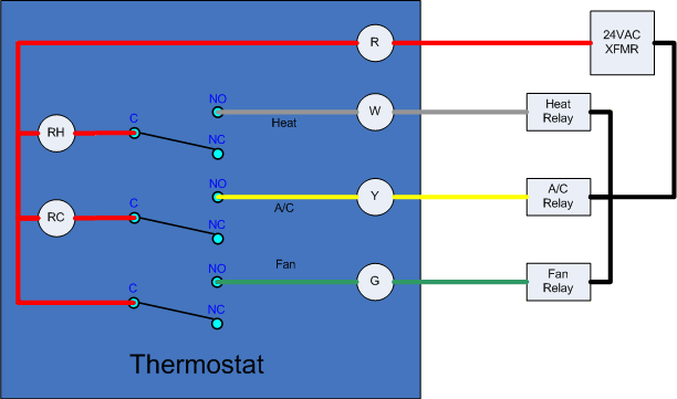
The relays are typically inside the boiler or heat pump that's being controlled. The wire shown as grey in this image is actually white. The switches shown inside the thermostat may be small mechanical or electronic relays, or may be a simple mechanical switch.