
Analog Sensors
'Analog Sensors' refer to sensors that are physically plugged into the 'Analog Sensor Input' connectors on the right side of the Vesta. There are many types of analog sensors, but the process of connecting, configuring, and calibrating is the same for all sensor types. The Vesta controller can accommodate any sensor type on any channel.
In this example we'll use the TS-1058 temperature sensor. These sensors work over a range from about -20°F to 212°F. They are inexpensive and widely used in Vesta installations. They have RJ11 connectors and plug directly into the analog sensor ports.
Connecting Sensors
The Vesta can accommodate a total of 8 analog sensors (16 for the Pro model). Sensors use telephone-style (RJ11) connectors. On the Vesta controller, sensor connections are arranged in groups of four. Sensors may be plugged directly into these connectors, or a sensor interface box may be used for sensors that don't have RJ11 connectors, or sensors that require scaling, amplification, or other signal conditioning. There are many interface boxes available - contact VECS to determine what is needed for your application.
There is also a fifth connector in each group. This is a standard Ethernet style (RJ45) connector that allows use of a sensor breakout box to connect four sensors. See the section below for details on the breakout box options.
Sensors are configured using the 'Configure I/O' tab on the Vesta controller web interface. This tab displays all of the possible inputs and outputs for the Vesta controller, and allows you to specify which inputs and outputs you will use in your application. Sensor inputs are identified as Analog Inputs on this page.
Because there are so many inputs and outputs, the Vesta controller allows you to specify which ones you're going to use. Only selected inputs and outputs are visible outside the 'Configure I/O' page. In the Vesta controller, the process of selecting a physical I/O involves three steps:
-
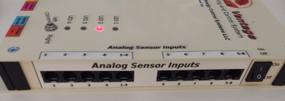
Identify the connector number on the outside of the controller where your sensor or other device is plugged in. The sensor inputs are on the right side of the Vesta controller and labeled with channel numbers from 1 to 16 (by default - different models may have different numbers of inputs). The picture above shows a sensor plugged into channel 1.
-
Find the corresponding line in the 'Configure I/O' page. In our example, the first line on the 'Configure I/O' page corresponds to Analog Input 1. To activate a channel, simply use the 'Type' pulldown to designate the type of sensor that's plugged into it. In this example, analog input 1 has a TS-1058 temperature sensor connected to it.
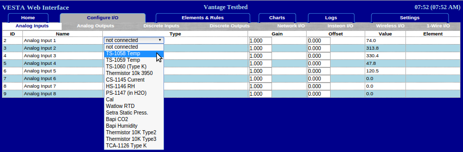
Figure 11.3: Configuring an Analog Sensor
For each sensor, make sure that the correct sensor type is selected. The most commonly used sensor in the Vesta controller is the TS-1058.
-
Finally, go to the 'Elements & Rules' tab and give your sensor a meaningful name. Here, we'll choose 'Room Temperature':
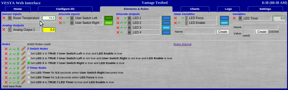
Figure 11.4: Renaming an Analog Sensor
As each sensor is added, check to see that a reasonable temperature is displayed. Holding the sensor between your fingers should result in a quick rise in displayed temperature.
Breakout Boxes
Breakout boxes are used to connect four sensors with a single cable. There are two types of sensor breakout boxes:
- The SB-1222 can be used if you have a group of sensors with RJ11 connectors at a remote location - in a nearby building, or on the roof, for instance. Rather than running four long individual sensor cables to the remote location, you can run a single Ethernet-style cable to the remote location, and then use the sensor breakout box to connect the individual sensors.
- The QUAD_INT can be used with sensors that don't have RJ11 connectors - thermistors, 4-20mA industrial sensors, or other sensors requiring individual wire connections to a terminal strip.
QUAD-INT Breakout Box
The Vesta QUAD-INT sensor interface allows up to four analog sensors to be connected using a single interface box. This can reduce clutter and congestion when using multiple non-VECS sensors. There are a few important considerations:
- Using the quad sensor interface does not increase the number of sensors that the Vesta can handle.
- The quad sensor interface does not work for the standard TS-1058 temperature sensor. Those sensors plug directly into the Vesta and don’t require an interface box.
- The quad sensor interface does not have all of the signals that are available on the individual sensor ports. Specifically, you can’t take advantage of the built-in thermistor scaling resistor, and differential sensors are not supported.
- The quad sensor interface requires some degree of customization before use - see the section below.
Connecting The Quad Interface
The quad sensor interface connects to one of the Vesta four channel RJ45 Analog Input connectors. They are labeled either ‘1-4’ or ‘5-8’ in the Analog Input area (the right side of the Vesta controller). The Pro model has two more labeled ‘9-12’ and ‘13-16’. The quad sensor interface must be connected using a Cat5 (Ethernet style) cable. To maintain color codes, white or gray is suggested. The terminal strip sections labeled 1 through 4 map to the analog channel numbers of the port where the Cat5 cable is connected - if the quad interface is plugged into the ‘5-8’ connector, terminal strip section 1 is analog input 5, 2 is 6, and so on.
Configuring
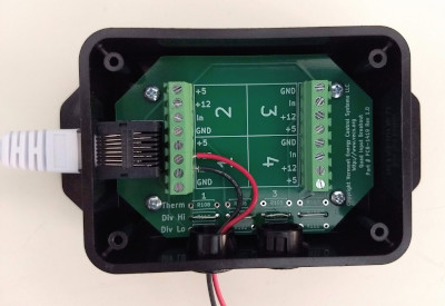
The quad sensor interface has 12 resistor locations along the bottom - 3 resistors for each sensor channel. These locations must be populated before the interface can be used. This is usually done by VECS prior to delivery.
Configuration is as follows:
‘Therm’ - this location must contain a thermistor scaling resistor if a thermistor will be connected. Contact VECS to determine the correct value for the thermistor to be used.
‘DIV HI’ - this is part of the resistor divider network used for sensors with outputs above 5.0 Volts. It must be a jumper for 4-20mA current loop sensors or 0-5V sensors.
‘DIV LO’ - this is the ground side of the restor divider network. This is populated only when connecting sensors with outputs above 5.0 Volts. Contact VECS to determine appropriate values.
Connecting Sensors
The quad sensor interface has four identical terminal sections, each with four signals. The +5, +12, and GND signals are electrically common to all four locations, while the ‘In’ signal is unique to each individual sensor. Common sensor types and their connections are as follows:
Sensors with DC voltage output. These typically have three wires - power, signal, and ground.
- Power is connected to +5 or +12 depending on the sensor’s requirements.
- Ground is connected to GND.
- Signal (or output) is connected to ‘In’.
Thermistors. These require a scaling resistor (see ‘Configuration’ above), and they have two wires with no polarity.
- One wire is connected to +5.
- The other is connected to ‘In’.
4-20mA sensors. There are a few variations in how these are configured. The most common type has two wires and will operate with a loop voltage of 12VDC. These require a piano switch inside the Vesta to be set for the corresponding input channel. The picture above shows a Vaisala 4-20mA humidity sensor connected to channel 1.
- Supply (often red wire) is connected to +12.
- Return is connected to ‘In’.
Calibration
The Vesta controller allows calibration of both gain and offset for each sensor. In most cases, calibration is not necessary. In the simplest case, you can specify a positive or negative offset to each channel to match the sensor reading to a know good value. Offsets are simply added to the measured temperature.
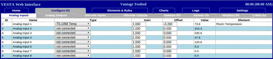
Figure 11.5: Calibrating an Analog Sensor
In the example above, we've added an offset of -.2 degrees to the Room Temperature sensor.
To get the highest possible accuracy, gain calibration can be done as well. To perform gain calibration, you need to establish two known temperatures that are as far apart as possible while remaining within the sensor's measurement range. The easiest way to do this is to use an ice bath and boiling water. Immerse the sensors in an agitated (stirred) bath of water packed with crushed ice. This will be very close to 0°C (32°F). Water at a vigorous boil will be very close to 100°C (212°F). If you're at a high altitude, you'll have to correct for altitude effects.
Use the sensor calibration page to calculate gain and offset. Follow the instructions in the spreadsheet - enter the actual low and high temperatures (use a reference thermometer if you have one, otherwise use freezing and boiling). Enter the readings for each sensor at low and high temperatures. The blue cells in the spreadsheet will then give you the values for gain and offset for each sensor. Enter those values in the Physical I/O tab.