
Initial Setup
This section deals with physical setup and initial power-on check.
It's usually a good idea to connect your new Vesta and make sure that everything is working and configured properly before installing it in its permanent location. This video is a quick (5 minute) overview of initial setup. It shows the Classic, but the process is the same for all models. The user interface differs slightly: refer to the web interface section of this manual.
There a few requirements for Vesta installation:
- A dry and relatively clean location
- A 110Vac wall outlet to plug the power supply into
- A network connection
- The configuration sheet that came with your Vesta
Network Connection
Internet access is not required, although it's desirable. At a minimum, a network connection of some sort is necessary for initial configuration the Vesta controller. Once it's set up, network access is not necessary.
If your Vesta has the Wi-Fi option, you'll still need a physical Ethernet cable during initial setup to configure the Wi-Fi.
Location
The Vesta controller must be installed in a dry location that does not experience condensation and where temperatures do not exceed 140 degrees Fahrenheit. Since it has no fan and is in an enclosure, dust is not a serious problem, although electrically conductive or corrosive dust should be avoided. It does not need to be physically near the equipment that is to be controlled, although it is desirable to choose a location that minimizes the length and installation effort of the cables between the Vesta controller and the equipment that is to be monitored and controlled.
No tools are required. However, it's very helpful to label sensor cables and other wires as they're connected. A labelmaker or wire labels are strongly suggested.
Physical Setup
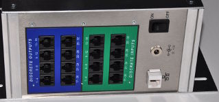
Figure 3.1: Side Panel with Power and Ethernet Connectors
Unpack the controller and place it in a convenient clean and dry location. It may be mounted on any horizontal or vertical surface that's protected from water. Initially, only network and power connections are needed. Plug an Ethernet cable into the white connector on the left side. Make sure that the power switch is in the 'Off' (down) position, and connect the wall-mounted power supply. The connector is next to the Ethernet port.
Turn on the power. If the Vesta controller is in its standard as-delivered configuration one of the LEDs on the front panel should illuminate after about 30 seconds.
Note: If your Vesta is part of a kit or if you ordered custom configuration, the front panel LEDs may not be present or may not illuminate.
Initial Connection
In the default configuration, the Vesta will automatically configure networking as needed for the network you connect it to. Once it has booted, you should be able to connect to it using the 'Internal Web URL' link on the configuration sheet that came with your unit. Start up a computer and open a web browser (Chrome, Firefox, Safari, Internet Explorer, or your favorite alternative). Get the configuration sheet that came with your Vesta and type the 'Internal Web URL' into your browser's URL bar. The URL will be in the form 'http://www.vecs.org/t.php?serial=xxxxxxxx'
After a brief delay, you should see your Vesta web interface:
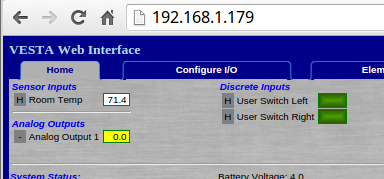
Figure 3.2: Home Page with URL
In this example, the IP address is 192.168.1.179 and the display shows configuration details that may differ from unit to unit. If this does not work, refer to the document on network troubleshooting.
At this point, plugging a temperature sensor into the first Sensor Input connector (right side, white connector group) should result in a display of the sensor's temperature.
Create Browser Bookmark
The IP address may change, so it's very helpful to create a bookmark using the URL from your configuration sheet. The mechanics of doing this vary depending on the browser that you use, but all of them support this process. Copy the URL text from the configuration sheet and create a bookmark with that text in your browser:
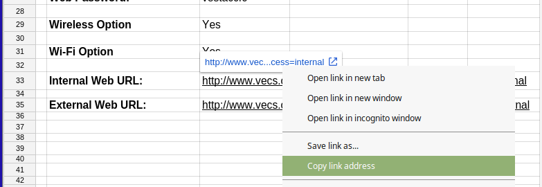
Figure 3.3: Copying Internal Web URL
The URL will be in the form 'http://www.vecs.org/t.php?serial=xxxxxxxx&access=internal', where 'xxxxxxxx' is your unit serial number. If you intend to access your Vesta from external locations (such as via SmartPhone or from work) bookmark the external web URL as well.