
Initial Setup
This section deals with physical setup and initial power-on check.
Requirements
There a a few requirements for Vesta installation:
- A dry and relatively clean location
- A 110Vac wall outlet to plug the power supply into
- A network connection (standard Cat5 cable)
The Vesta controller must be installed in a dry location that does not experience condensation and where temperatures do not exceed 140 degrees Fahrenheit. Since it has no fan and is in an enclosure, dust is not a serious problem, although electrically conductive or corrosive dust should be avoided. It does not need to be physically near the equipment that is to be controlled, although it is desirable to choose a location that minimizes the length and installation effort of the cables between the Vesta controller and the equipment that is to be monitored and controlled.
Internet access is not required, but is desirable. At a minimum, a crossover cable can be used to connect the Vesta controller directly to a computer. A computer with a web browser is needed to configure and program the Vesta controller. Once it's set up, network access is not necessary.
No tools are required. However, it's very helpful to label sensor cables and other wires as they're connected. A labelmaker or wire labels are strongly suggested.
Physical Setup
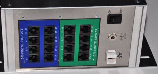
Unpack the controller and place it in a convenient clean and dry location. It may be mounted on any horizontal or vertical surface that's protected from water. Initially, only network and power connections are needed. Plug an Ethernet cable into the white connector on the right side. Make sure that the front panel power switch is in the Off (down) position, and connect the wall-mounted power supply. The connector is next to the power switch.
Turn on the power. If the Vesta controller is in its as-delivered configuration, one of the green LEDs on the front panel should illuminate after about 30 seconds.
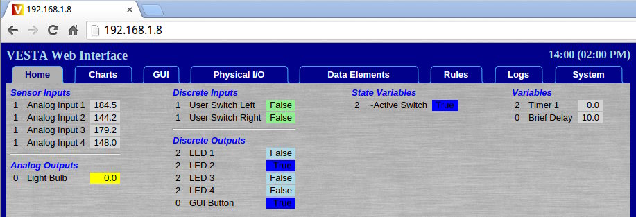
The Vesta controller has a pre-assigned IP address that should allow it to be visible on your network. This address (a number like 192.168.1.8) is on the configuration sheet that is included with the controller. Start a web browser on your computer (Chrome, Internet Explorer, Firefox, Safari) and type the IP address of the Vesta controller into the URL bar. Press 'Enter' and the Vesta controller home page should appear. Depending on the browser, you may need to preface the IP address with 'http://' - http://192.168.1.8, for instance.
Once you have the controller displayed on your browser, bookmark the address.
In this example, the IP address is 192.168.1.8 and the display shows configuration details that may differ from unit to unit. If this does not work, refer to this document on network troubleshooting.
At this point, plugging a sensor into the first Sensor Input connector (right side, white connector group) should result in a display of the sensor's temperature. The pages in the web interface do not refresh automatically - you'll have to click the tab (or click reload on your browser) to display fresh data.
Web Interface
In almost all cases, all configuration and interaction with the Vesta controller is through a web interface. The Vesta controller has a built-in web server which provides access to the system. The next section of the manual will briefly cover each of the tabs in the web interface.