Vermont Energy Control Systems

Practical monitoring and control for the real world

User Manual - Vesta Classic | Vermont Energy Control Systems

Vermont Energy Control Systems

Practical monitoring and control for the real world

Introduction

This document is intended to help with initial setup and use of the Vesta Classic system Controller. It covers physical setup, electrical connections, and access to the built-in web interface. In addition to this document, there are additional companion documents:

  1. Rule Programming - creating rules to control external devices
  2. Graphical User Interface - creating custom 'live' graphical user interfaces

Historical Note: The Vesta controller is an evolution of an earlier control system that was known as the 'NoFossil Control System'. As such, there may be references to 'NFCS' in the documentation or in other places. For all intents and purposes, 'NFCS' can be considered synonymous with 'Vesta'.

Disclaimer: This documentation is under construction. Every effort is being made to ensure that it is accurate and complete. However, it is entirely possible that it may contain errors and omissions. If you see a problem, please contact Vermont Energy Control Systems.

User Manual - Vesta Classic | Vermont Energy Control Systems

Vermont Energy Control Systems

Practical monitoring and control for the real world

Initial Setup

This section deals with physical setup and initial power-on check.

Requirements

There a a few requirements for Vesta installation:

  1. A dry and relatively clean location
  2. A 110Vac wall outlet to plug the power supply into
  3. A network connection (standard Cat5 cable)

The Vesta controller must be installed in a dry location that does not experience condensation and where temperatures do not exceed 140 degrees Fahrenheit. Since it has no fan and is in an enclosure, dust is not a serious problem, although electrically conductive or corrosive dust should be avoided. It does not need to be physically near the equipment that is to be controlled, although it is desirable to choose a location that minimizes the length and installation effort of the cables between the Vesta controller and the equipment that is to be monitored and controlled.

Internet access is not required, but is desirable. At a minimum, a crossover cable can be used to connect the Vesta controller directly to a computer. A computer with a web browser is needed to configure and program the Vesta controller. Once it's set up, network access is not necessary.

No tools are required. However, it's very helpful to label sensor cables and other wires as they're connected. A labelmaker or wire labels are strongly suggested.

Physical Setup

A picture of the Vesta Classic's ports

Unpack the controller and place it in a convenient clean and dry location. It may be mounted on any horizontal or vertical surface that's protected from water. Initially, only network and power connections are needed. Plug an Ethernet cable into the white connector on the right side. Make sure that the front panel power switch is in the Off (down) position, and connect the wall-mounted power supply. The connector is next to the power switch.

Turn on the power. If the Vesta controller is in its as-delivered configuration, one of the green LEDs on the front panel should illuminate after about 30 seconds.

The Vesta controller has a pre-assigned IP address that should allow it to be visible on your network. This address (a number like 192.168.1.8) is on the configuration sheet that is included with the controller. Start a web browser on your computer (Chrome, Internet Explorer, Firefox, Safari) and type the IP address of the Vesta controller into the URL bar. Press 'Enter' and the Vesta controller home page should appear. Depending on the browser, you may need to preface the IP address with 'http://' - http://192.168.1.8, for instance.

A screenshot of the Vesta web interface

Once you have the controller displayed on your browser, bookmark the address.

In this example, the IP address is 192.168.1.8 and the display shows configuration details that may differ from unit to unit. If this does not work, refer to this document on network troubleshooting.

At this point, plugging a sensor into the first Sensor Input connector (right side, white connector group) should result in a display of the sensor's temperature. The pages in the web interface do not refresh automatically - you'll have to click the tab (or click reload on your browser) to display fresh data.

Web Interface

In almost all cases, all configuration and interaction with the Vesta controller is through a web interface. The Vesta controller has a built-in web server which provides access to the system. The next section of the manual will briefly cover each of the tabs in the web interface.

User Manual - Vesta Classic | Vermont Energy Control Systems

Vermont Energy Control Systems

Practical monitoring and control for the real world

Home Tab

The home page displays current values for all configured inputs and outputs. It also displays the most recent system messages. Refreshing the home page will refresh the values as well. The home page does not have any security, since it provides only a passive view of system data.

A screenshot of the Vesta Home Tab

Top Section

The top portion of this page shows the current value for each input, output, and variable in the system, collectively referred to as 'data elements' in this document. The number next to each data element identifies the system task that's responsible for providing the value that you see. For example, task 1 manages hardware inputs. Task 2 is the rule engine. Any data element with a zero next to it gets its value from the user - there's no system task that will provide a value. This is covered in more detail in the programming guide.

System Status

This section shows the last four system warnings and informational messages. These can be helpful in diagnosing a system problem. 'Start time in the future' messages can be safely ignored.

Rules

This section lists all the rules that have been defined. Any active rule will have a red dot next to it. This can help quickly show what's happening with the system.

Control Panels

At the bottom of the page there are links to two graphical control panels. These are covered in the GUI section of this document.

User Manual - Vesta Classic | Vermont Energy Control Systems

Vermont Energy Control Systems

Practical monitoring and control for the real world

Chart Tab

This tab contains a charting tool that lets you explore logged data. This tool is still in development at this time, so all features may not work perfectly. Refreshing the page may solve some problems.

By default, it shows data for the past two hours. Analog values are plotted in two dimensions in the top portion of the chart. Discrete values are shown in the bottom section as lines that are thin when the discrete is off (false) and thick when it's on (true).

The buttons along the top let you look at the past 2, 6, 12, 24, or 48 hours with a single click. The blue arrows at either side of the timeline let you page forwards or backwards by one 'page'.

Clicking a start time and an end time on the timeline will zoom in to that interval.

Hovering over a trace key along the right side will highlight that trace. Clicking on a trace will remove it.

All data elements that changed during the displayed interval are shown immediately to the right of the chart. If an element is already displayed on the chart, it will be in bold. Clicking on an element will toggle it between being displayed and not being displayed.

Any data elements that did not change during the displayed interval are shown farther to the right. Each shows the value that it had during the chart display interval. They can be charted if desired, but since the value didn't change it will not be particularly interesting.

A screenshot of the Vesta Chart Tab

User Manual - Vesta Classic | Vermont Energy Control Systems

Vermont Energy Control Systems

Practical monitoring and control for the real world

GUI Tab

The Vesta automatically creates and updates two Graphical User Interfaces (GUIs). One is a read-only version (it doesn't provide the ability to change the value of any data element). It's essentially a status display. The second is a control panel - it allows the user to change the value of any variable or hardware output. The control version is of course password protected - the username is 'vesta', and the password is on the configuration sheet that comes with your system.

The control page is an excellent tool for testing during initial setup. Before there are any rules, you can turn any output on and off simply by clicking on it.

Clicking on the GUI tab toggles between the two. The control version displays discrete outputs (and state variables) as round buttons rather than square boxes. Analog outputs and standard variables are shown as text input fields. This is what the read-only status display version looks like:

A screenshot of the Vesta GUI Tab

User Manual - Vesta Classic | Vermont Energy Control Systems

Vermont Energy Control Systems

Practical monitoring and control for the real world

Physical I/O Tab

The Vesta has a large number of channels of physical I/O, and only a fraction will be used in any single installation. To keep from cluttering every page with unused channels, the Vesta only displays channels that are actually in use. This tab is where you identify which channels you wish to use.

For sensor inputs and analog outputs, there are a wide range of devices that might be plugged in. This tab is where you configure each channel by identifying what's plugged into it.

Depending on the software version you are running, there may be a single page or there may be a page for each I/O type.

The details of setting up specific I/O types are covered later, but in all cases the first step is to identify a channel that you want to use and click 'Create Element' on the line for that channel.

A screenshot of the Vesta Physical I/O Tab

This tab also provides the opportunity for sensor calibration.

User Manual - Vesta Classic | Vermont Energy Control Systems

Vermont Energy Control Systems

Practical monitoring and control for the real world

Data Elements Tab

'Data Elements' is the Vesta term for any data that can be used in rules or in status displays. A data element may be temperature from a sensor, the state of a thermostat from a discrete input, the state of a circulator controlled by the Vesta, or the value of an internal variable that the Vesta uses in its rules.

This tab is where you can assign user-friendly names to the Vesta physical I/O channels. You can also create variables and assign values to them.

A screenshot of the Vesta Data Elements Tab

This screenshot is from our Smart Dollhouse trade show exhibit.

User Manual - Vesta Classic | Vermont Energy Control Systems User Manual - Vesta Classic | Vermont Energy Control Systems

Vermont Energy Control Systems

Practical monitoring and control for the real world

Front Panel

A picture of the front panel of the Vesta

Along the right side of the front panel there are four LEDs and a small three-position switch. As delivered, the LEDs and switches are connected to Vesta discrete inputs and outputs. There are also some simple rules defined that illuminate LEDs based on switch position. Try moving the switch and observe what happens to the LEDs and to the Vesta controller web interface.

This switch and these LEDs can be used for any desired purpose. In particular, they are good for developing and testing rules before assigning the rule to real hardware. The LEDs are often used as visual indicators of system status, and the switch can be used to manually set operating modes ('Summer' vs. 'Winter', for example).

System Settings

Clicking the 'System' tab on the web interface brings up a page where some basic system settings can be configured. Each section of this page will be covered in detail later in this manual. For initial setup, the most important setting is the 'Centigrade' checkbox. While the system can be switched between Centigrade and Fahrenheit at any time, any numeric values used in rules will NOT be converted and will have to be manually re-entered in the new units. For instance, if the system was originally programmed in Fahrenheit and there was a rule to turn on a circulator any time room temperature dropped below 70 degrees, the rule would have dramatically different effects if the system were then changed to Centigrade. 70°C is a pretty high room temperature! It's important to choose units at initial setup to avoid this problem.

A screenshot of the Vesta System tab

Make any changes and click 'Update'. Changes take effect immediately.

User Manual - Vesta Classic | Vermont Energy Control Systems

Vermont Energy Control Systems

Practical monitoring and control for the real world

Sensors

A picture of a sensor plugged into channel 1 of the Vesta

Sensor Types

There are three commonly used sensor types for the Vesta controller - general-purpose TS-1058 temperature sensors, TS-1060 thermocouples, and TS-1061 thermistor sensors. There are many other types, but these cover most applications. They are electrically quite different, but the Vesta controller can accommodate any sensor type on any channel.

The TS-1058 sensors work over a range from about -20°F to 212°F. They are inexpensive and in the Vesta controller they provide a temperature resolution of better than a tenth of a degree Centigrade.

The TS-1060 sensors are standard type K thermocouples. They require an external amplifier (part number TCA-1125). They can measure temperatures from 32°F to about 2500°F.

As configured for the Vesta controller, the TS-1061 sensors cover the range from about 40°F to over 300°F (limited by melting of the cable insulation). Because thermistors are highly nonlinear, they provide much better resolution at lower temperatures. At room temperature their resolution is better than a tenth of a degree, but at boiling the resolution is only about a quarter of a degree Centigrade. They are smaller than the TS-1058 sensors and can fit in tight spaces.

Connecting Sensors

The Vesta can accommodate a total of 16 sensors. Sensors use telephone-style (RJ11) connectors. On the Vesta controller, sensor connections are grouped into four rows with four connectors on each row. Sensors may be plugged directly into these connectors.

There is also a fifth connector on each row. This is a standard Ethernet style (RJ45) connector that allows use of a sensor breakout box. A breakout box can be used if you have a group of sensors at a remote location - in a nearby building, or on the roof, for instance. Rather than running four long individual sensor cables to the remote location, you can run a single Ethernet-style cable to the remote location, and then use a sensor breakot box to connect the individual sensors. For each row of four sensors on the Vesta, either the individual connectors OR the breakout box may be used - not both.

Physical I/O Tab

Sensors are configured using the 'Physical I/O' tab on the Vesta controller web interface. This tab displays all of the possible inputs and outputs for the Vesta controller, and allows you to specify which inputs and outputs you will use in your application. Sensor inputs are identified as Analog Inputs on this page.

Because there are so many inputs and outputs, the Vesta controller allows you to specify which ones you're going to use. Only selected inputs and outputs are visible outside the 'Physical I/O' page. In the Vesta controller, the process of selecting a physical I/O involves three steps:

  1. Identify connector number on the outside of the controller where your sensor or other device is plugged in. For instance, the sensor inputs are on top right side of the Vesta controller and labeled with channel numbers from 1 to 16 (by default - different models may have different numbers of inputs). The picture above shows a sensor plugged into channel 1.

  2. Find the corresponding line in the 'Physical I/O' page. In our example, the first line on the 'Physical I/O' page corresponds to Analog Input 1. To use a physical I/O in the Vesta controller, you must select it by clicking the 'Create Element' link in the rightmost column of the 'Physical I/O' page. In this example, an element has already been created and assigned the name 'Analog Input 1'.

    A screenshot of the Physical I/O Tab showing the element "Analog Input 1"

    For each sensor, make sure that the correct sensor type is selected. The most commonly used sensor in the Vesta controller is the TS-1058.

  3. Finally, go to the 'Data Elements' tab and give your sensor a meaningful name. Here, we'll choose 'Boiler Outlet Temp':

    Screenshot of Data Elements tab showing the 'Boiler Outlet Temp' element

As each sensor is added, check to see that a reasonable temperature is displayed. Holding the sensor between your fingers should result in a quick rise in displayed temperature.

Calibration

The Vesta controller allows calibration of both gain and offset for each sensor. In most cases, calibration is not necessary. If calibration is desired, an offset calibration is usually all that's needed. Offsets are simply added to the measured temperature.

To get the highest possible accuracy, gain calibration can be done as well. To perform gain calibration, you need to establish two known temperatures that are as far apart as possible while remaining within the sensor's measurement range. The easiest way to do this is to use an ice bath and boiling water. Immerse the sensors in an agitated (stirred) bath of water packed with crushed ice. This will be very close to 0°C (32°F). Water at a vigorous boil will be very close to 100°C (212°F). If you're at a high altitude, you'll have to correct for altitude effects.

A screenshot of the Physical I/O Tab with a number of sensors set up

Use the sensor calibration page to calculate gain and offset. Follow the instructions in the spreadsheet - enter the actual low and high temperatures (use a reference thermometer if you have one, otherwise use freezing and boiling). Enter the readings for each sensor at low and high temperatures. The blue cells in the spreadsheet will then give you the values for gain and offset for each sensor. Enter those values in the Physical I/O tab.

User Manual - Vesta Classic | Vermont Energy Control Systems

Vermont Energy Control Systems

Practical monitoring and control for the real world

Relays

Relay Basics

Relays are key components of most electrical control systems, and the Vesta controller is designed to operate up to 32 relays.

While detailed relay theory is beyond the scope of this manual, there is a tutorial document on this site, and there are many online explanations such as this one.

Relays are typically used for two purposes:

  1. Control - To allow the Vesta controller to control some external device such as a valve or a circulator
  2. Sense - To allow the Vesta controller to sense the presence of electrical power that's provided by some other means, such as another controller. For instance, a relay could be used to detect that an oil boiler was running.

Control relays have 12Vdc coils and are directly controlled by the Vesta controller. Each control relay is driven by a discrete output.

Sense relays have coils that match the voltage that needs to be sensed. For instance, a relay that's used to sense whether a 120VAC pump is running would use a 120VAC coil wired in parallel with the pump motor. The relay contacts would in turn be connected to a Vesta discrete input. An example is described in this application note.

Control Relays

The Vesta controller discrete outputs can drive any relay that has a DC coil that operates at 12 Volts and draws less than 200ma of coil current. This includes virtually all 12Vdc relays.

External Relay Enclosure

A picture of the RM-1207 External Relay Enclosure

It is desirable to keep high voltages outside of the Vesta controller enclosure for three reasons:

  1. To avoid accidentally vaporizing expensive circuit boards
  2. To keep the Vesta controller enclosure intrinsically safe and finger-friendly
  3. To reduce the distance that power has to travel to get to the high voltage loads

To achieve these goals, the preferred approach to controlling high voltage loads is to us a relay enclosure that is mounted near the loads and controlled by the Vesta controller. This relay enclosure can contain any combination of control and sense relays. The most common use of external relays is typically control, so the standard external relay enclosure is set up with control relays.

Since each discrete output connector on the Vesta controller carries four channels, the capacity of an external relay box is four relays.

The RC-4DD (formerly RM-1207) relay module has an RJ45 connector for connecting to Vesta discrete outputs. Internally, each relay has two electrically separate sets of contacts, each with common (C), Normally Open (NO), and Normally Closed (NC) contacts. These are brought out to screw terminals for easy connection to electrical devices.

Wiring

A picture of the internal workings of a control relay

The RC-4DD is connected to any Discrete Output connector on the Vesta Controller using standard Cat5 Ethernet cable. The Vesta color code for discrete outputs is blue, so a blue cable is suggested.

The screw terminals in the relay module can accommodate up to 12 gauge stranded and 14 gauge solid wire if necessary, but smaller gauges are much easier to accommodate in the limited internal space.

As with all high voltage wiring, ensure that all relevant codes are followed.

WARNING: To avoid damage to the Vesta controller, disconnect the Vesta controller cable from the relay box before doing any wiring.

Sample External Control Relay Application

There is an application note that describes controlling a high voltage device with a Vesta discrete output using a relay.

User Manual - Vesta Classic | Vermont Energy Control Systems

Vermont Energy Control Systems

Practical monitoring and control for the real world

Discrete Inputs

The Vesta provides 32 channels of discrete inputs. These inputs are intended to be connected to dry contacts - that is, electrical contacts which do not have any voltage or power source connected to them. Examples would be switches, microswitches, some thermostat contacts, snap-action thermal switches, and magnetic door and window switches (as used on alarm systems).

If you're not sure whether a set of contacts qualifies as 'dry contacts', check with a handheld Voltmeter (in both AC and DC settings) when the switch is in both positions.

In the Vesta, discrete inputs are provided in groups of four. Standard Cat5 (Ethernet type) cables are used to connect discrete inputs to the Vesta. A common use of discrete inputs is to monitor relay contacts in RI-1209 and RI-1210 sense relay boxes. There's an application note that covers an example of this.

User Manual - Vesta Classic | Vermont Energy Control Systems

Vermont Energy Control Systems

Practical monitoring and control for the real world

Discrete Outputs

As with discrete inputs, the Vesta provides 32 channels of discrete outputs grouped into sets of four, connected using standard Cat5 cable. The Vesta discrete outputs provide 12 Vdc at up to 200ma, suitable for driving most 12vdc relays as well as small buzzers and LEDs.

In most cases, discrete outputs are simply connected via Cat5 cable to our RC-4DD (formerly RM-1206 or RM-1207) relay modules. However, our discrete breakout box provides screw terminals for connecting other devices.

User Manual - Vesta Classic | Vermont Energy Control Systems

Vermont Energy Control Systems

Practical monitoring and control for the real world

Variable Speed Control

The Variable Speed Control Unit is typically mounted next to the device that's being controlled in order to keep high voltage wire lengths to a minimum. There is a light gauge cable connecting the Variable Speed Control unit to the Variable Speed Breakout Box that's typically mounted next to the Vesta controller. This cable uses a standard RJ11 connector on the Vesta controller end and is hard-wired to the control unit. The example photos here are for a benchtop demo and use standard appliance line cord for the high voltage (115vac) wiring. Actual installations would typically use armored BX cable or a code-compliant equivalent.

Configuring the Control Unit

DIP Switches

A picture of the dip switches in the Nimbus

The heart of the Control Unit is the 'Nimbus' manufactured by Control Resources. In the Vesta controller application, it's configured to be controlled by a 4-20ma signal. The DIP switches should be set according to the picture at the right - switches 1, 2 and 7 on and the rest off.

Jumper

A picture of the jumper in the Nimbus

There's also a jumper which needs to be installed on the two pins nearest the edge of the card. This photo is courtesy of Smokeless Heat in Pennsylvania. They use the Vesta controller with an interesting Swedish boiler, and have quite a bit of experience with the Nimbus variable speed controller.

The Nimbus is a quite sophisticated device. There is a complete manual available from Control Resources.

Connecting Power and Load

A picture of the wiring connecting power and load

The Control Unit requires connection to both 115vac and the load that is to be controlled. These connections are made as shown in the photo below, The load is to the left and is connected to the red and black wires at the left end of the row of wires (when viewed as shown). The next two wires (black and white) are connected to 115vac power.

Connecting the Control Signal

A picture of the wiring connecting the control signal

The last connection that's required is the control signal from the Variable Speed Breakout Box. This signal will be provided via an RJ11 cable (typically flat 4 conductor). If the standard 4 conductor color code is used, the signal is on black and yellow, corresponding to pins 1 and 4. If six conductor cable is used, the control is on pins 2 and 5.

The black wire (pin 1) is connected to the purple wire on the control unit, and the yellow wire (pin 4) is connected to the gray wire. Because the signal wires are so small, use cable ties to tie the signal wires to the control unit wires as shown.

User Manual - Vesta Classic | Vermont Energy Control Systems

Vermont Energy Control Systems

Practical monitoring and control for the real world

Terminology

Basic Terminology

I/O: Input and Output

Discrete: An electrical input or output which can be in one of only two states, generally corresponding to 'on or 'off'.

Analog: An electrical input or output which can have a wide range values. Analog inputs are typically used to measure values such as temperature.
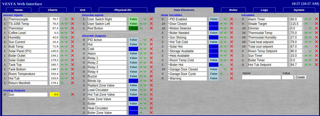
TRUE and FALSE

The Vesta controller is at its core a computer, and it processes rules as a computer does. In the physical world, a pump may be on or a contact may be closed or a coil may be energized. Inside a computer, these states have to be represented as TRUE or FALSE values. The Vesta controller uses TRUE and FALSE in the following ways:

TRUE means 'on' or 'non-zero' or 'active'. The implication is that something is happening.

  • For contacts, TRUE means 'closed'.
  • When a discrete output is TRUE, power is being supplied to the relay coil, LED, or whatever the discrete output is driving.
  • For a timer or any numeric value, TRUE means non-zero.

FALSE means 'off' or 'zero' or 'inactive'.

  • For contacts, FALSE means 'open' - no current is flowing.
  • When a discrete output is FALSE, no power is being supplied.
  • For timers and numeric values, FALSE means zero.

TRUE and FALSE are not typically used with temperatures or other values that can have a fractional part, because the results can be unexpected. A temperature of 0.001 degrees will display as '0', but is actually non-zero and will be treated as TRUE.

Electrical Connection and Signal Types

The Vesta controller is designed to connect electrically to a variety of physical devices. Electrical connections are divided into four broad categories:

  1. Power. Electrical power to run or operate a device.
  2. Communication. Etherenet, USB, or other connections used to transmit data between intelligent devices.
  3. Analog. Electrical signals that can have a range of values. The output of a typical temperature sensor would be an example.
  4. Discrete. Electrical signals that can have only two values such as off/on, open/closed, or active/inactive. Also called digital signals.

The Vesta controller uses all four categories. Power is straightforward, and communication is usually only the Ethernet connection. The bulk of the connections (and complexity) are the analog and discrete signals.the Vesta controller supports both inputs and outputs for these types of signals. They're typically used as follows:

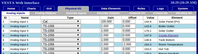
Analog Inputs are to read temperature and other types of sensors that can measure a range of values.

Analog Outputs provide a signal that can be used to drive certain pumps, fans, or valves to variable speeds or positions.

Discrete Inputs are typically used to detect contact closure. Each discrete input consists of a pair of wires. If the input wires are shorted together, the input is sensed as 'TRUE'.

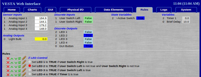
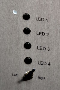
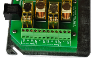
Discrete Outputs provide the ability to turn on or activate an external device such as a relay or an LED. A discrete output that's on provides 12 Volts.

All programming and control of the Vesta controller is accomplished through the use of these four electrical signal types.
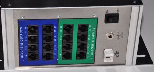
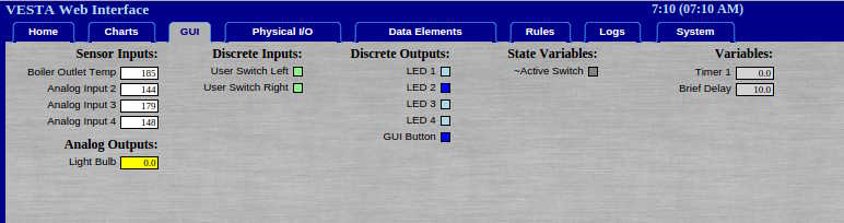
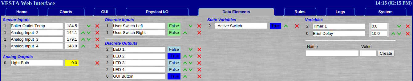
Colors

For external connectors, colors are used where possible to help minimize the chances of plugging the wrong cable into the wrong connector. Each signal type has a unique color as follows:

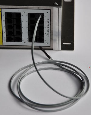
  • Analog Inputs are grey (or white)
  • Analog Outputs are yellow
  • Discrete Inputs are green
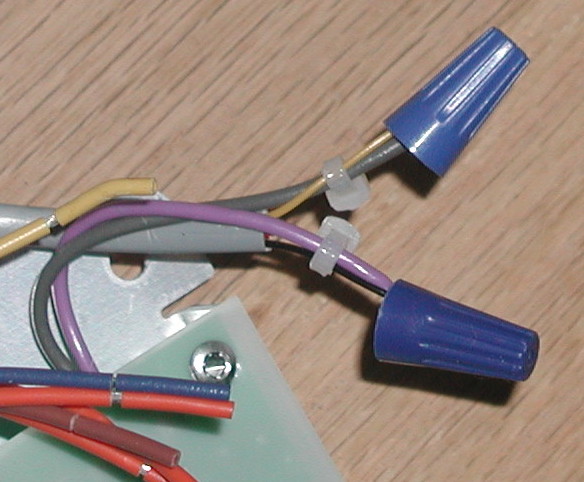
  • Discrete Outputs are blue

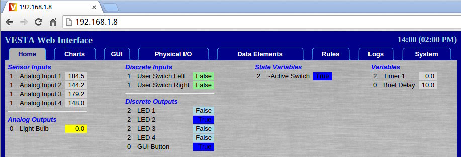
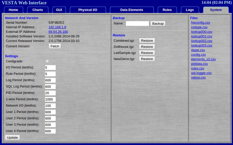
These colors are also used in the web interface when displaying values for discrete inputs and outputs. While it's not required, using matching cables will help prevent mistakes.

Inside the controller, red is +5V, yellow is +12V, and black is ground. There are some exceptions, but this convention is used where possible.

Connectors

RJ45: The Vesta controller uses standard RJ45 connectors for some of the I/O. These are 8 conductor connectors that are used for Ethernet cables. The male connector is easily crimped onto standard Ethernet cable with an inexpensive tool. The female connector is designed to snap into a panel (such as a wall plate) and is known as a 'keystone' connector. Electrical connection to the female connector is accomplished by pressing wires into slots in the back of the connector with another inexpensive device called a 'punchdown' tool.

RJ11 and RJ12: These are the connectors that are often used for telephone cables. They have positions for six conductors, but often only four are used. They look identical to RJ45 connectors, except that they are narrower. A connector that uses all six conductors is called RJ12, while a connector that only uses the middle four conductors is called RJ11.