Appendix B
Heat transfer in heat exchangers is a very complex topic. In this case, we did not have any specifications for the heat exchanger, so we can only model heat transfer one each side of the heat exchanger independently, and make reasonable assumptions about the performance of the heat exchanger itself.
Heat Transfer Equations
Water weighs 8.34 lbs/gal and 1 BTU will raise 1 lb of water 1℉. The equation for heat transfer is therefore:
BTU/hr = Gallons/Minute * Minutes/Hour * Pounds/Gallon * (T1-T2)
BTU/hr = Gallons/Minute * 60 * 8.34 * (T1-T2)
Solving for DeltaT (T1-T2):
(T1-T2) = BTU/hr / (Gallons/Minute * 60 * 8.34
Solving for flow rate:
Gallons/Minute = BTU/hr / ((T1-T2) * 60 * 8.34)
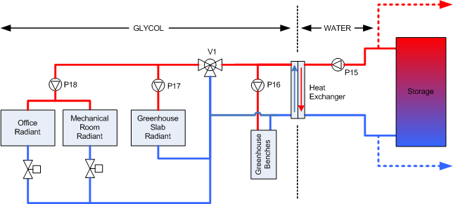
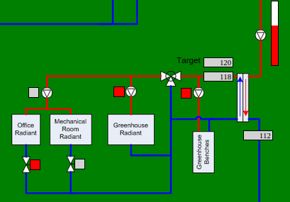
Greenhouse Zones
The greenhouse has four zones. BTU loads are from the design documents. Office and bench flow rates are actual measured values. Note that the bench zone can be supplied with water at two different temperatures and presents a different BTU load depending on supply temperature.
| Zone | Temp Supply | BTU Load | Flow Rate |
| Office | 120 | 5000 | 2gpm |
| Mech Room | 120 | 5000 | 2gpm |
| Slab | 120 | 110,000 | 9gpm |
| Benches | 120 | 30,000 | 4gpm |
| Benches | 150 | 70,000 | 4gpm |
Using the equation for Delta T above, we can calculate the drop in temperature that we would expect from each zone, and the resulting return temperature:
| Zone | Supply Temp | BTU Load | Flow Rate | Delta T | Return Temp |
| Office | 120 | 5000 | 2gpm | 5 | 115 |
| Mech Room | 120 | 5000 | 2gpm | 5 | 115 |
| Slab | 120 | 110,000 | 9gpm | 24 | 96 |
| Benches | 120 | 30,000 | 4gpm | 15 | 105 |
| Benches | 150 | 70,000 | 4gpm | 35 | 115 |
Under peak load conditions, the greenhouse is supplied with hot Glycol at 120℉, and the return temperature will be about 100℉, with a total heat load of about 150,000 BTU/hr.
Supply (Hot Water) Side
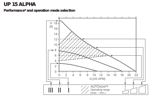
The supply side of the heat exchanger is fed with hot water at about 170℉. In the original configuration, P15 was a fixed-speed circulator delivering about 10gpm. This was reasonable at peak load, but with smaller heat demands it resulted in 10gpm of very hot water being returned to the bottom of storage:
| Condition | Supply Temp | BTU Load | Flow Rate | Delta T | Return Temp |
| Office Only | 170 | 5000 | 10gpm | 1 | 169 |
| Peak Load | 170 | 150,000 | 10gpm | 30 | 140 |
Predicted Values
The ideal flow rate under these conditions would be slow enough to minimize the return temperature to storage. If the heat exchanger has adequate surface area, we might be able to achieve a return temperature on the hot water side that's close (perhaps 10℉ above) to the return temperature on the Glycol side:
| Condition | Supply Temp | BTU Load | Glycol Return Temp | Target Water Return Temp | Flow Rate |
| Office Only | 170 | 5000 | 115 | 125 | 0.2gpm |
| Slab & Bench | 170 | 140,000 | 100 | 110 | 4gpm |
| Peak Load | 170 | 150,000 | 100 | 110 | 6gpm |
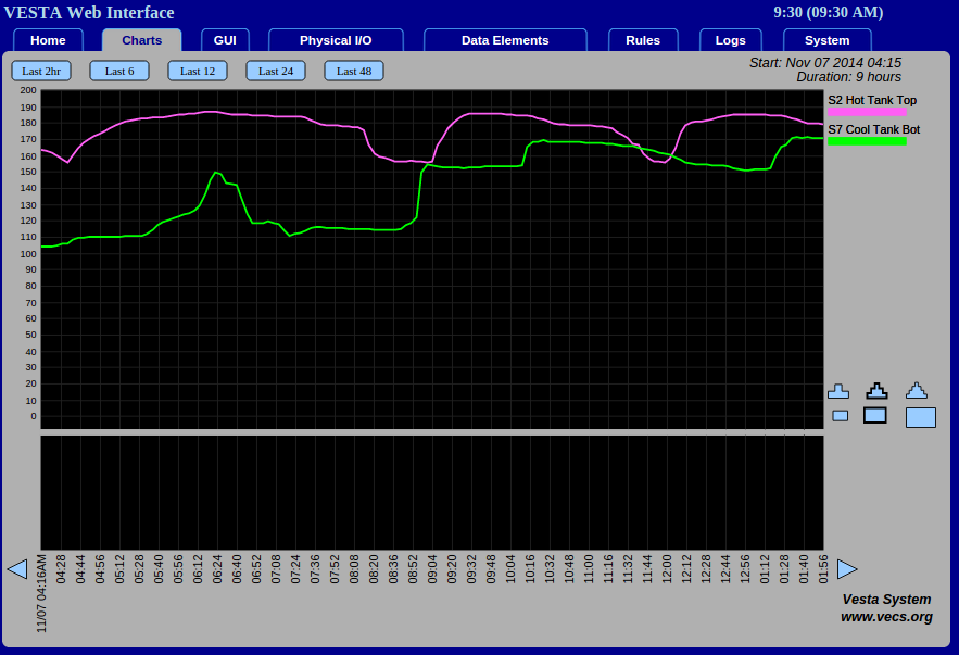
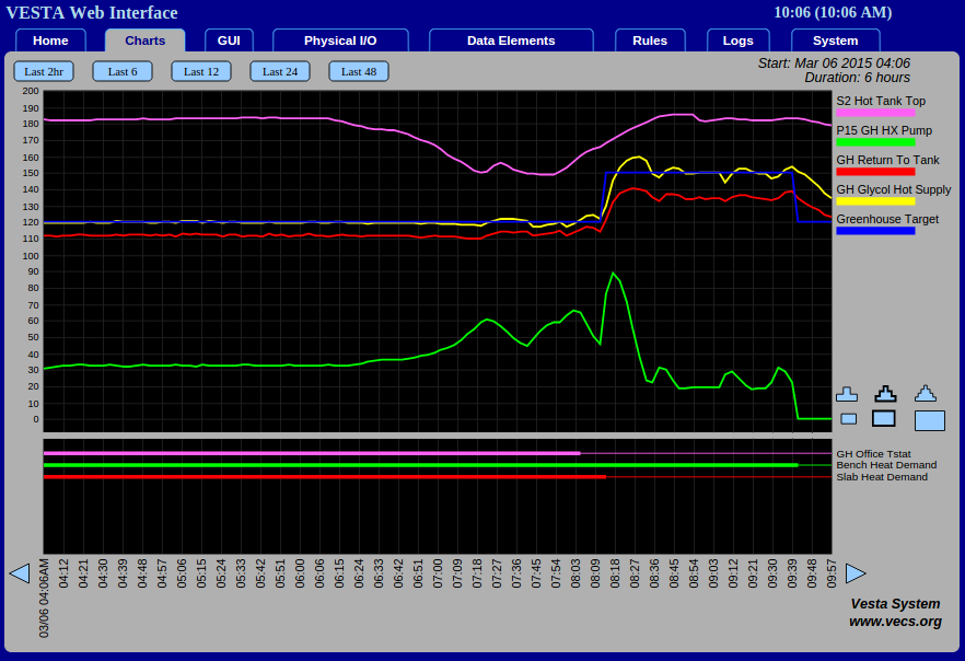
Observed Values
Logged data for office only and combined slab and bench zone operation shows good correlation with predicted values. Note that circulator speed is only available as a percentage of electrical drive signal, which does not have a linear relationship with actual flow rate. At this time, peak load conditions have not been observed.
| Condition | Supply Temp | BTU Load | Glycol Return Temp | Water Return Temp | Flow Rate |
| Office Only | 180 | 5000 | 100 | 110 | 5% |
| Slab & Bench | 180 | 140,000 | 100 | 110 | 30% |
| Peak Load | | 150,000 | | | |