Vermont Energy Control Systems

Practical monitoring and control for the real world

Monitor a Pump

Monitor a Pump | Vermont Energy Control Systems

Vermont Energy Control Systems

Practical monitoring and control for the real world

Monitor a Pump

Monitor A High-Voltage Device

Sometimes it's useful to monitor a device that you don't directly control. It could be the burner in an oil boiler, an attic ventilation fan, living room lights - almost anything. In this example we'll monitor a simple sump pump that's controlled by a float switch. We'd like to know whether it's running, how often it runs, and how long it runs. We'd also like to trigger an alarm if it runs too long since that means that there might be a problem.

There are several possible ways to do this. In this case we'll use the RI-110A (formerly RI-1209) Relay Input Module. This unit has four relays in it, each with a 110VAC coil. One set of contacts on each relay is connected to the Vesta, allowing the Vesta to detect if the relay has been activated.

We'll connect the coil of one relay in parallel with the sump pump motor so that the relay is energized when the pump is running. Here's a schematic view - we've added the two wires shown as dotted lines.

A diagram of the setup desired A pisture of the inside of the relay box

When the sump pump motor is turned on, power is applied to the relay coil. That closes the relay contacts. Since one contact set is connected to a Vesta discrete input, the Vesta can detect that the relay has been energized. The other contact set is available for any other desired purpose - perhaps a low-voltage indicator light if desired.

NOTE: This is only a concept drawing. All wiring must be performed in accordance with applicable codes. Final design is the responsibility of the system designer or installer.

Wiring

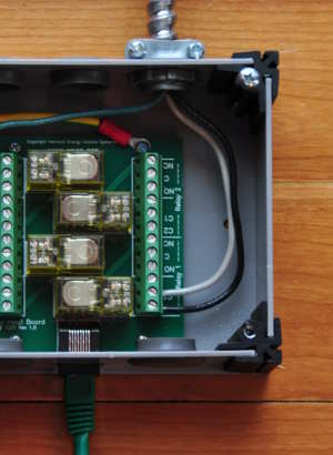
Wiring in this case is very simple - there are just two connections as shown in the schematic above. We're using relay 1, which is at the bottom right corner. The relay coil is AC, so there's no polarity - either wire can go to either coil connection. The green Cat5 cable at the bottom goes to a Vesta discrete input connector - we'll use the one labeled '5-8'.

At this point, physical setup is complete. The next section covers setting up the discrete input and rules on the Vesta.

Monitor a Pump | Vermont Energy Control Systems

Vermont Energy Control Systems

Practical monitoring and control for the real world

Monitor a Pump

Vesta Setup

We need to set up the Vesta to be aware of our relay. There are only two steps required:

  1. Identify the new input channel
  2. Give it a user-friendly name

The first step is done on the 'Physical I/O' tab. We're using the first relay in a group of four that are connected to inputs 5-8. That means our relay is on input 5. Select 'Discrete Inputs' and click 'Create Element' on the line for discrete input 5:

A screenshot of the Phsycial I/O tab with emphasis on Discrete Element 5 in the Elements List

The second step is to give it a reasonable name. 'Sump Pump' would be appropriate. Click the 'Data Elements' tab. NOTE: On the Vesta Vantage and Pro, the Data Elements tab and the Riules tab are combined. Find 'Discrete Input 5' and rename it to 'Sump Pump':

A screenshot of Discrete Element 5 being renamed to Sump Pump

At this point, the sump pump status is visible on the user interface. It's being logged every minute. It can be viewed on charts and used in rules.

Rules

Rules are covered in depth in the Rule Programming Manual. We'll show an example here without detailed discussion of rule behavior.

We wanted to send an alarm if the pump is on for too long. This will require three steps:

  1. Create a timer variable
  2. Create a timer rule
  3. Create an alarm rule

Go to the 'Data Elements' tab and create a variable named 'Sump Timer'. This will be used in the timer rule that we create next.

A screenshot of the user creating a variable named Sump Timer

After letting the system run a couple of days and studying the data, we see that the sump pump never runs for more than three minutes. We conclude that if it was to run for more than five minutes, that would indicate a problem and we'd want to know about it. In this example we'll set up a five minute timer, and send an email if the pump is still running after five minutes.

We create a rule that continuously sets our timer variable to 300 seconds any time the pump is NOT running. As soon as the pump turns on, the timer will start to count down. If it reaches zero, our warning email will be sent. NOTE: Of course, use your own email address in this rule.

Set Sump Timer for 300.0 seconds when Sump Pump is false. When Sump Timer is not true send warning to demo@vecs.org

At this point we're done. The Vesta will monitor our sump pump, log data about it, make status visible locally and remotely, and it will send us an email if there's a problem.